Start assembling

Start assembling the magnets

All operations are carried out under power off.
To avoid scratching the surface of the LED module, please put foam underneath.

 LED Screen ,LED Videowände – Ihre Digital Signage Lösung

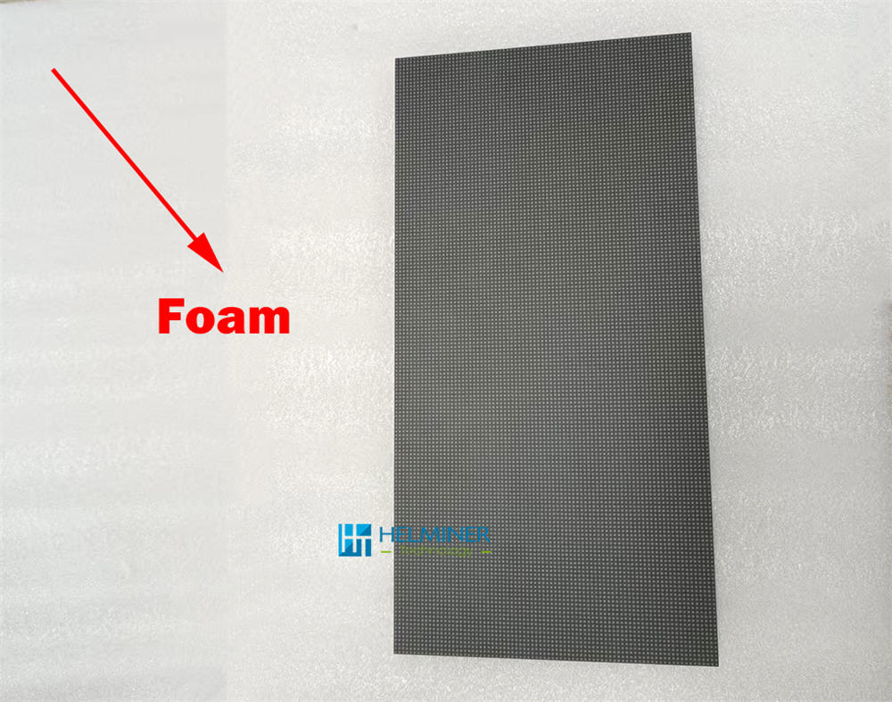
Lay the modules face down and flat,
do not stack them to avoid damage.
Prepare the magnets and start assembling.

Please do not directly touch or collide with any metal objects on the back of the electronic components to avoid static damage .

 LED Screen ,LED Videowände – Ihre Digital Signage Lösung

 LED Screen ,LED Videowände – Ihre Digital Signage Lösung

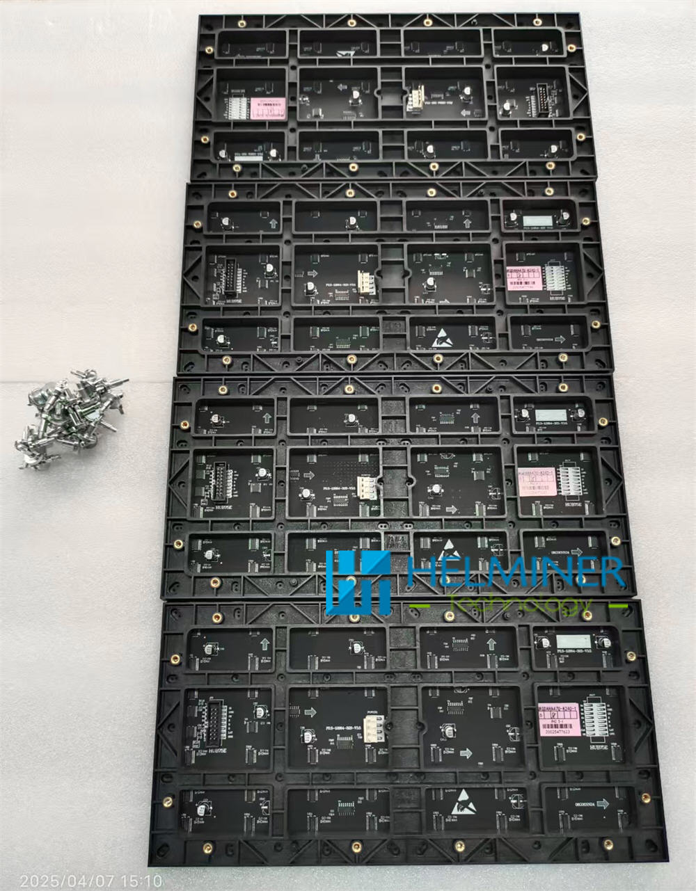
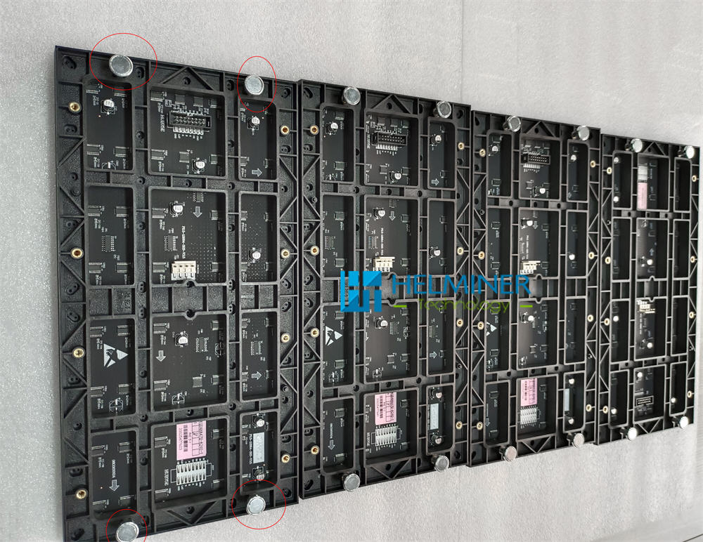
Each module is equipped with 4 magnets, which are ready for use after installation.
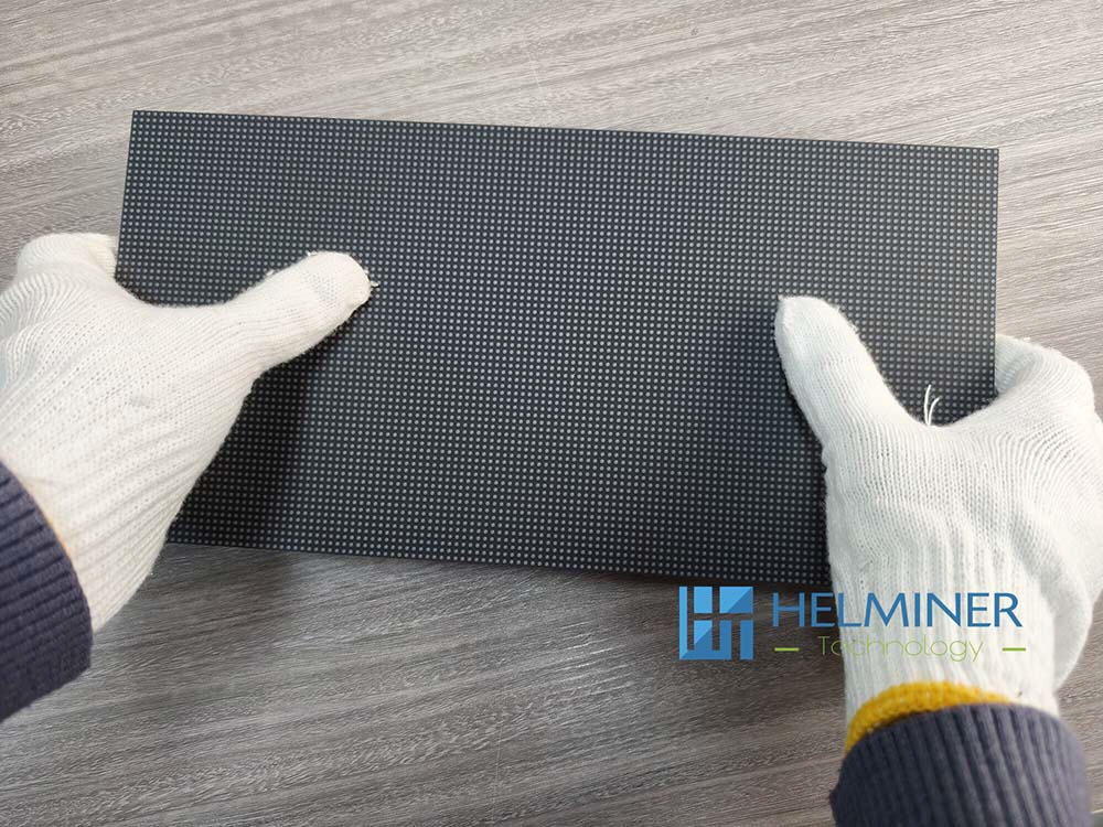
Basic Learning Sample LED WALL Have two different configurations . Therefore, their structures are also different.


A : 9 Rows * 2 Columns

B : 6 Rows * 3 Columns

Please first prepare the supporting structure of the LED WALL according to the reference CAD drawings we provide.

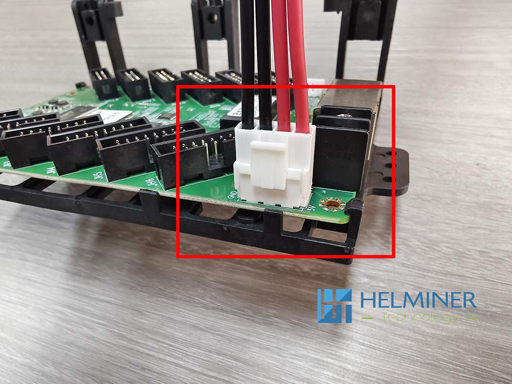
Start INSTALLATION POWER AND Data Card

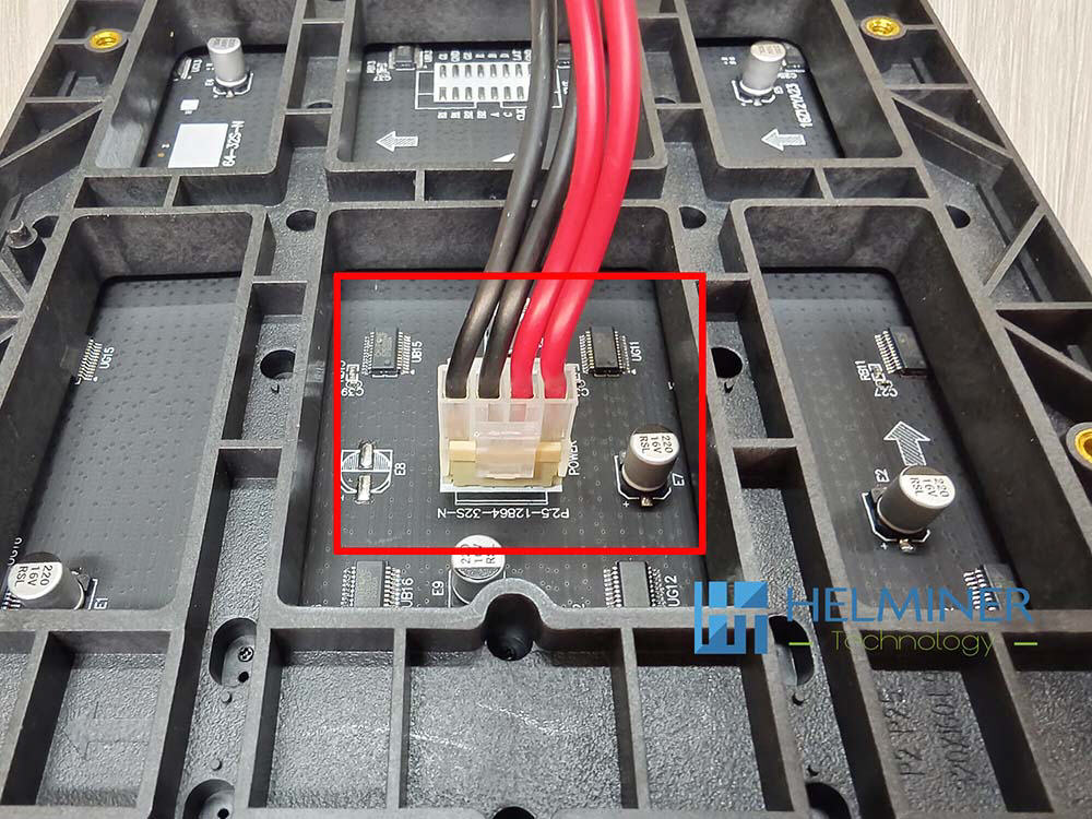
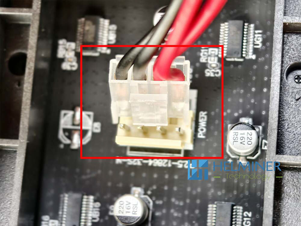
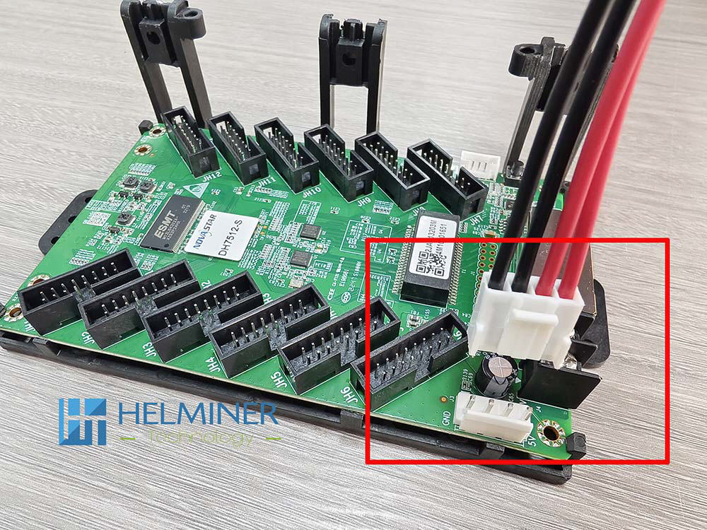
  1. Install the power cable and data card cable to the 5V port of the power supply in advance
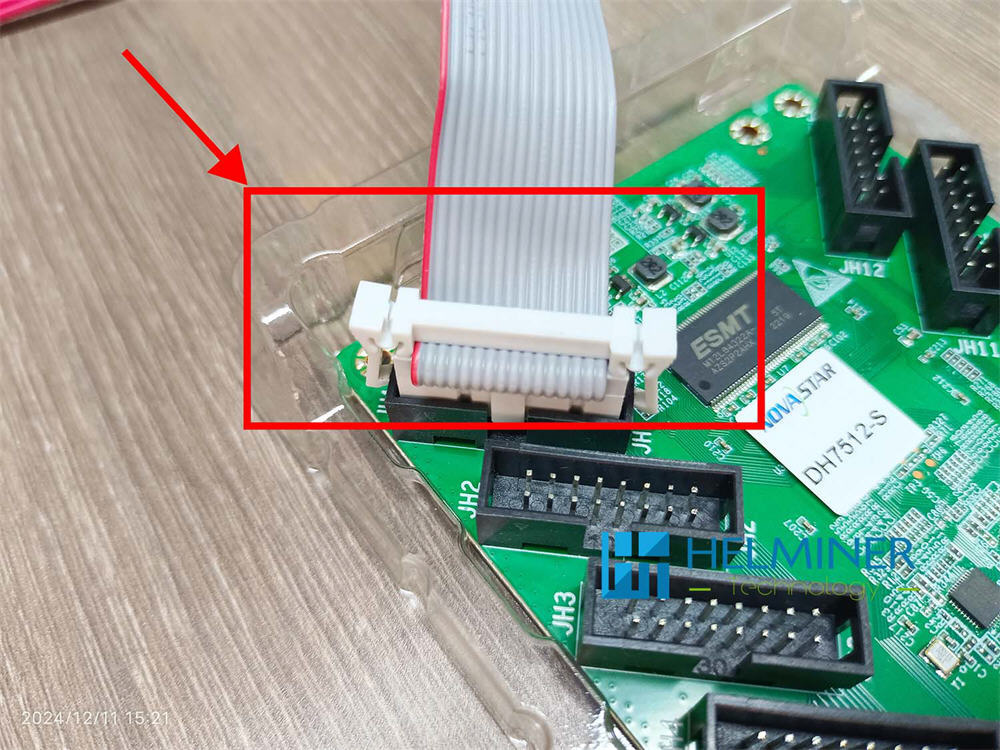
  2. Install the flat data cable to the corresponding position of the DATA CARD according to the drawing
  3. Fix the power supply and data cards to the support structure according to the reference position in the drawing.
  4. Connect the 220V input power cable of the LED POWER according to the connection sequence in the drawing
  5. After the installation is complete, perform a preliminary inspection,
    and then power on and check if everything is correct.
    After confirming everything is correct, turn off the power.
  6. Installation the LED Display Module
  7. Updating ....
How to Connect ?
The data cable has a positive and negative insertion direction, which must be consistent with the direction in the picture. There is a square protruding port that is consistent with the concave port.

The connection of the power cord is also direction-dependent, please refer to the position of the red frame in the picture.

Start by lighting up a cabinet | 640*480mm ( 2 * 3 pcs LED Module ) For example by A series

Wear gloves when touching the front of the display to avoid scratching the display surface.

Make sure the arrow is facing upwards when installing.


One power supply 6pcs LED module + 1pcs receiver data card

This sample box use the JH1, JH2, JH3, JH7, JH8,JH9 6 DATA-PORT

Finished product display

The completed cabinet viewed from the front .
The positions of the data interface and the unit board must be exactly the same as in the picture.

Connect the LED cabinet to TB2 LED Wall controller . TB2 LED Wall controller to Computer.

Home > LED Wall Blog > LED Wall Sample Box - User Information